- Bez kategorii (21)
- Codes Scratches (4)
Additional audio input Creative Inspire T3000 mod
In this post I would like to describe my mod for Creative Inspire T3000 2.1 system. My problem was that I was unable to connect 2 or more audio source to my set (at my case it was the notebook + home server + pc box).
At the beginning, I was thinking about building an active audio mixer and putting it inside the Creative case. This idea didn’t work because of two reasons: I’m too lazy, and the second reason is that there is no open electronics shop at 2am in my town 🙂 So, finally I decided to build sth from the old elements that I have on my stock. The final and realized solution is a passive audio mixer, built only from a few resistors and two capacitors. I was a little scarred that I might lose the signal in the passive circuit, but the audio cards generally produce the signal with ~1V amplitude, and the amplitude needed to drive the amplifier is around 0,775 volts. So in my case it was OK.
Overview
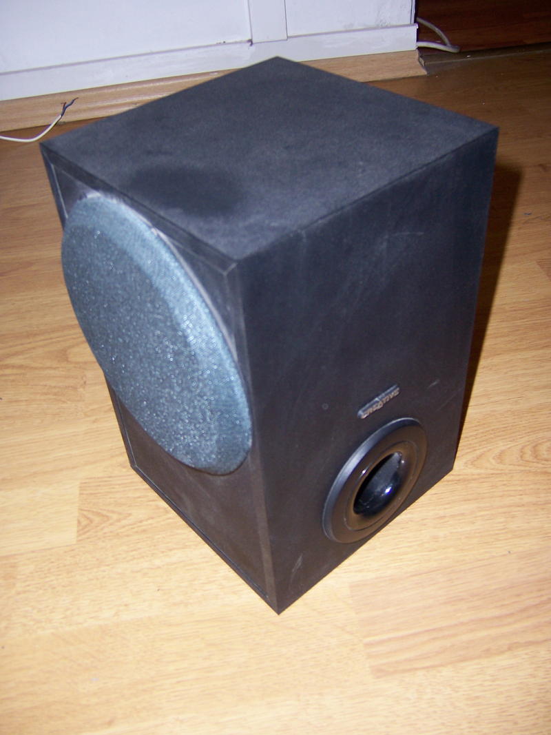
And here is a shot of my set before mod:
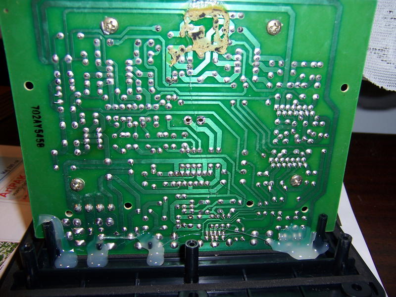
In the back of the case, we have a panel which is mounted by six screws, having unscrewed them… I expected to remove the panel with the attached PCB. However, that did not happen, because Creative uses a lot of strange mousse-glue to eliminate the problem with vibration.
I think that the vibration problem could have been resolved much better. So, Creative! Thumbs down for this! After a failed attempt to remove the speaker (I tried to get inside the case this way), I just removed this whole panel with pcb by force.
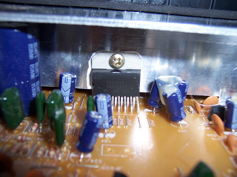
On the pcb we have a typical application of TDA7378 amp. One thing that was strange for me, was the power supply method. I expected that after turning off the speakers by moving the volume knob, the power supply would be cut off. But that did not happen! The whole circuit is still powered and only goes to sleep mode.
Input circuits
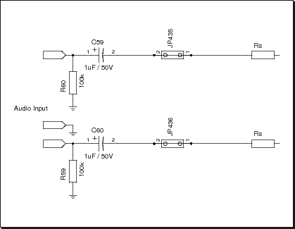
Original audio input from Creative looks like this:
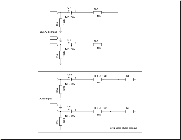
For the beginners, I will explain what it is and what it does. JP435 and JP436 are just wires (simple connection) – these jumpers will be later used for mod. Capacitors C59 and C60 are used for separating the inputs and they cut off the DC from the input signal. It conducts only alternating voltage. In other words it conducts only AC signals and cuts off all the DC ones. R59 and R60 resistors are used for discharging the C59 and C60 after the fading of the signal or power off / on. This way they protect from the appearance of unwanted spikes. The resistors marked on the figure above as Rs are not important for us, I just put them there because we will use them as “mixing capacitors”.
Mod
Below there is a scheme of the input circuits after my mod:
As shown on the scheme, the JP435 and JP346 have been replaced by 10k resistors, and the whole input circuit was duplicated, and the outputs are connected on Rs resistor pads.
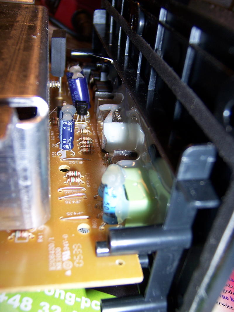
Below there are a few pictures of this modification.
List of materials:
- Resistors: 4 x 10k, 2x100k
- Capacitors: 2x 1uF@50v
- Jack 3.5mm stereo socket
- Tools: soldering iron, drill, pliers
- Materials: tin, chunk of wire, cyanoacrylate glue

